
- #Common cathode 7 segment display how to#
- #Common cathode 7 segment display pro#
- #Common cathode 7 segment display code#
Number A B C D E F G PORTDĪs shown in above table, we sends the hex value of the number to the PORTD of Pic microcontroller that we want to display. This table shows 7 segment encoding for pic microcontroller programming. We generated this table which contains bit patterns for all numbers from 0-9. We send bit patterns to turn on and off specific segments according to the number that we want to display. For instance, in this interfacing, we used the PORTD of PIC18F4450 microcontroller. To write code, first, we need to create a pattern that shows numbers by sending specific patterns to 7 segment display from PIC18F4450 microcontroller.

#Common cathode 7 segment display how to#
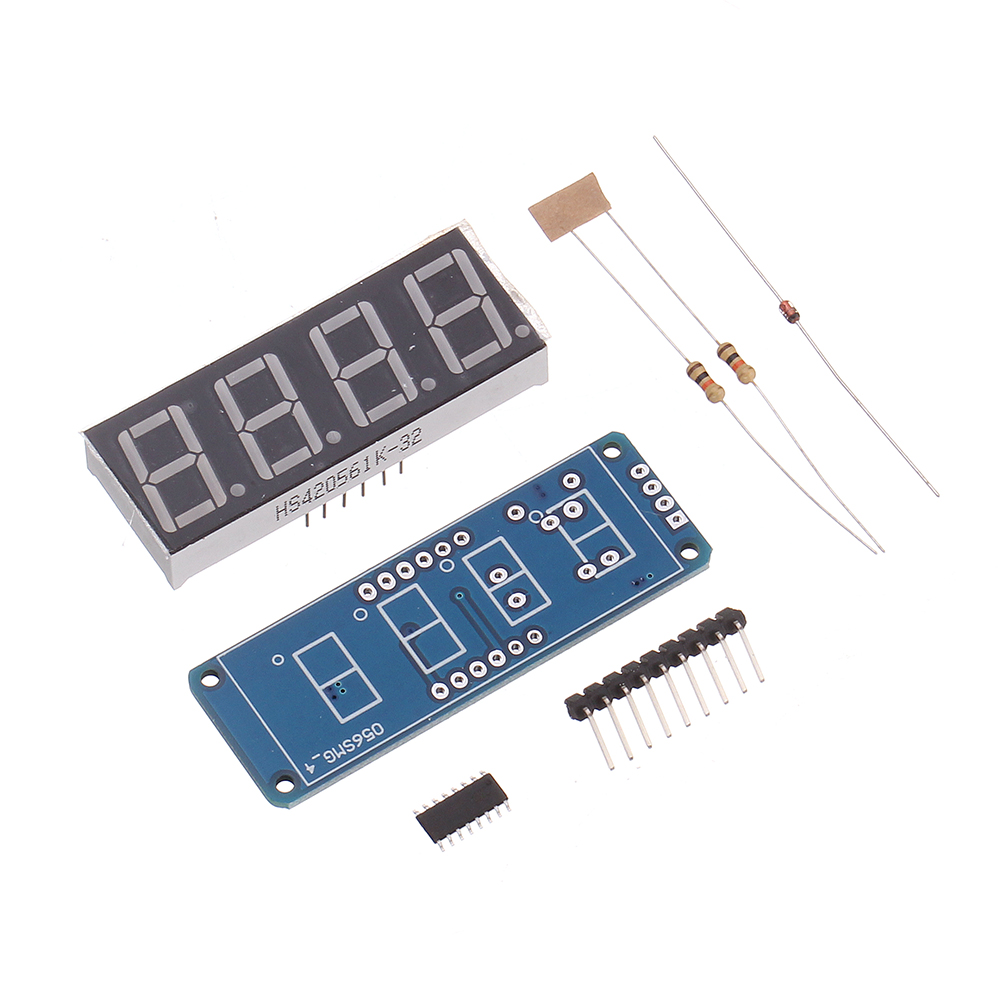
This video teaches how to create project in MPLAB XC8 compiler If you are a beginner with MPLAB XC8 compiler, we recommend you to check this video. If we use a common anode type, the common terminal will be conned to 5 volts or Vcc. Because of all GPIO pins of PIC18F4550 microcontroller can provide a maximum of 25mA current and also each segment LED needs only 10mA current to operate. These resistors are the current limiting resistors. This interfacing circuit used 330-ohm resistors for connection. Therefore, we connect a common terminal to the ground reference. This picture shows a connection diagram of 7 segment display with pic microcontroller. We will use MPLAB XC8 compiler for programming. In this section, we will see an example of 7 segment displays interfacing with pic microcontroller. 7 Segment Display Interfacing with Pic Microcontroller in MPLAB XC8 It requires a simple interface similar to an LED interfacing tutorial. As you know that we can easily interface 7 segment displays with a pic microcontroller by using GPIO pins of PIC microcontroller as digital output pins. In previous sections, we have seen that how to control 7 segments displays. Note: If we use common anode type 7 segment display, control signals (a-g) will be active low (ground reference) and similarly for common cathode type, control signals are always active high level ( usually 5 volts). Similarly we can display other numbers by controlling respective light-emitting devices. For example, if we want to display 1, we turn on segments ‘b’ and ‘c’ and to display 2, we turn on segments a, b, g, d, and e. Each segment is referred with the name from a to g. By controlling specific lights, we can display numbers from 0-9. To turn on a specific segment in common cathode mode, we connect that pin to the voltage or to a logic high level with a microcontroller How to control 7 segment Display with Pic Microcontroller?Īs we mentioned earlier, it consists of 7 light-emitting devices that are arranged in a rectangular design box. In common cathode display, all the cathode connections of the LEDs are tied together which forms the common pin that needs to be grounded. To turn on a specific segment, we connect that pin to the ground or logic low level. In common anode display, the positive pins of all the LEDs are tied together to form the common pin which needs to be provided a ‘HIGH’ signal that means 5 volts signal. As you can see from this diagram, it consists of 10 pins.Ī common pin is also associated with the 7-segment, which is used to identify the type of 7-segment display whether it is the common anode or a common cathode. Another additional 8 th LED named ‘dp’ is also present sometimes in a 7-segment display which is used to illuminate a dot or a decimal point. Each LED is known as a segment and it is assigned a name from ‘a’ to ‘g’. Seven segments, as the name suggests, consist of seven LEDs organized in a specific pattern. Simplest, because its working is easy to understand and its interface with the microcontroller is quite straight-forward. Seven segment display is regarded as the most basic and simplest electronics display device. We will see examples with two compilers such as MPLAB XC8 compiler and MikroC Pro. In this tutorial, we will start with an introduction of 7 segment displays? How to interface a 7-segment display with PIC microcontrollers.
#Common cathode 7 segment display code#
#Common cathode 7 segment display pro#


 0 kommentar(er)
